Why High-Performance Carrier Rollers Fail Long Before the Track Looks Worn
Component selection, fitment and the connections that keep an undercarriage working as a system.
On this page
A carrier roller can appear simple from the outside: a steel shell, a shaft, seals, and a rotating surface supporting the upper track run. Yet premature roller failure rarely begins with one visible defect. It often starts earlier—through inconsistent steel quality, a distorted machined bore, insufficient hardened depth, or a sealing surface that looked acceptable before the machine entered mud, shock loading, and abrasive dust.
Last updated:

For fleet managers and undercarriage buyers, the difficult part is that two excavator carrier rollers may look nearly identical at installation. The meaningful differences emerge over operating hours, when track alignment, rotating resistance, wear pattern, leakage, and shell deformation begin to separate a controlled manufacturing route from a merely acceptable one. This paper follows the manufacturing logic behind factory-direct carrier rollers, from forging or casting selection through CNC machining, induction hardening, assembly, and final inspection.
high performance carrier roller manufacturing
Why Carrier Roller Manufacturing Matters in the Field
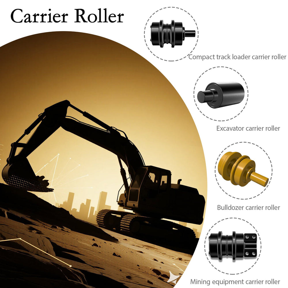
A carrier roller does more than support the top section of the track chain. It helps control track travel, limits unwanted chain movement, and keeps the undercarriage working within its intended alignment under changing loads.
In actual operation, rollers face repeated impact from track links, abrasive contamination, rainwater, temperature changes, and vibration transmitted through the track frame. A shell that is hard but lacks a resilient core may crack or chip. A roller with good steel but poor machining concentricity may wear unevenly and create track guidance problems. The manufacturing standard therefore needs to connect material, geometry, heat treatment, sealing, and assembly rather than treat them as isolated checkpoints.
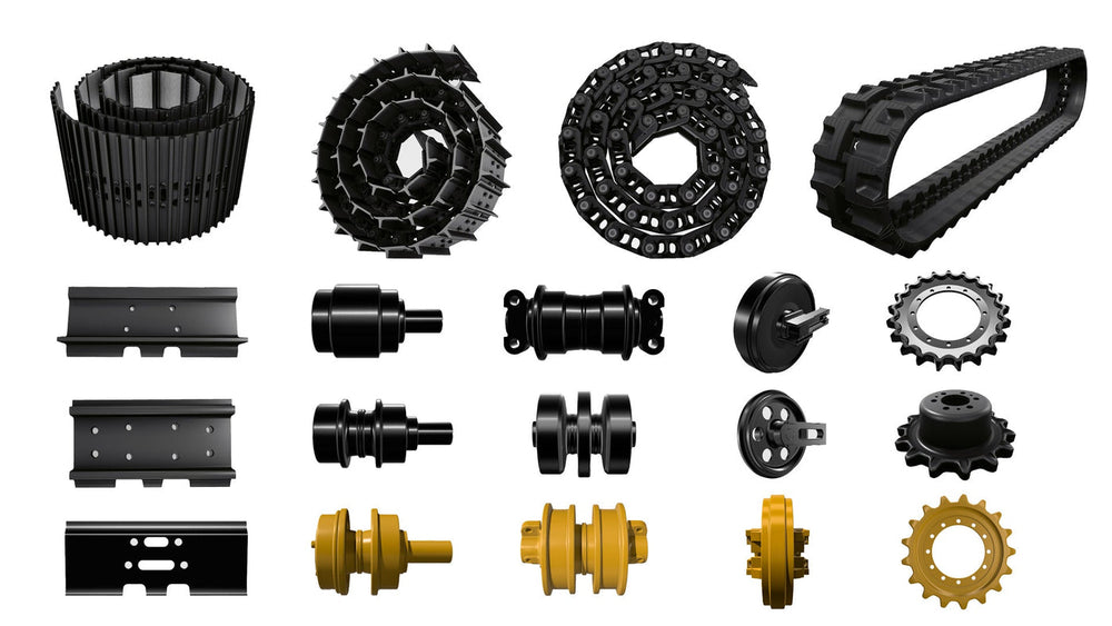
KTSU works across an undercarriage range of more than 3,000 items for construction and agricultural equipment, which creates a practical view of how fitment, duty cycle, and track system condition affect roller outcomes. A carrier roller is not judged only by its appearance at dispatch; it is judged by how predictably it behaves alongside the chain, idler, sprocket, and frame.
The Carrier Roller Process Route From Steel to Assembly
A controlled carrier roller route begins with defining the steel grade, forging or casting method, machining allowances, heat-treatment plan, and inspection requirements before production starts. The correct sequence reduces the risk of solving a structural problem later with extra machining or superficial hardness.
A typical Kunshan factory process route follows this logic:
Raw-material verification, including material identification and chemistry control
Precision casting or forging blank preparation
Rough machining to establish primary datums
Shell joining where the roller design uses two half-shell forgings
Stress relief or intermediate thermal processing where required
CNC turning of the outer diameter, bore, seal seats, and end faces
Induction hardening of the working surface
Tempering, cleaning, and hardness verification
Shaft, bushing, seal, and lubrication assembly
Rotation, leakage, dimensional, and visual inspection
Traceability marking, preservation, and packing
The route matters because later stages depend on earlier ones. If forging stock has excessive variation, CNC machining must remove uneven material and may reduce the intended wall section. If the shell distorts during welding or thermal processing, a finished roller can meet a basic diameter measurement while still carrying runout that affects the track in service.
Forging, Casting, and the Choice of Roller Blank
Forging is often selected for high-load roller shells because the process can support a dense, controlled material structure suited to repeated impact and fatigue. Precision casting may be appropriate for certain shapes or production requirements, but it requires careful control of solidification, internal soundness, machining stock, and inspection criteria.
For high-performance carrier rollers, the decision should not be framed as “forged is always better” or “cast is always cheaper.” The relevant question is whether the selected route matches the roller geometry, required surface-hardening profile, machine duty cycle, and acceptance plan. A casting route can fail when shrinkage, inclusions, or insufficient local wall control are not detected before machining. A forging route can also disappoint when billet quality, forming temperature, grain flow, or cooling discipline varies between batches.
KTSU’s published roller production method describes shells composed of two forged semi-roller sections, joined using NITTO friction welding alongside automated and robotic CO2 welding processes. This approach places particular importance on joint integrity, concentricity, and the management of heat effects before final machining.
What CNC Machining Actually Controls
CNC turning is where the carrier roller becomes a functional rotating component rather than a rough steel shell. The outer running surface, internal bore, end faces, shaft interfaces, and seal locations must relate accurately to the same datum strategy.
The critical issue is not simply whether a machine can achieve a narrow tolerance on one dimension. It is whether the bore, outside diameter, and seal surfaces remain concentric after welding, heat treatment, and final finishing. A roller may rotate freely on a bench yet generate uneven contact in service if runout or face squareness shifts the load toward one side of the track path.
Key machining control points commonly include:
Outer-diameter profile and cylindricity
Bore diameter and roundness
Concentricity between bore and running surface
End-face squareness
Seal-seat finish and edge condition
Shaft fit, axial clearance, and interface geometry
Surface finish on locations that retain lubrication or contact seals
Operators sometimes replace a noisy roller and assume the replacement part alone caused a repeat issue. In reality, track tension, track-frame wear, bent guards, mismatched roller geometry, or an incorrectly fitted part can accelerate wear even when the CNC work is sound. That is why dimensional verification must be paired with equipment-specific fitment control.
Induction Hardening Must Balance Wear and Toughness
Induction hardening creates a wear-resistant outer layer on the roller’s running surface while retaining a tougher internal section beneath it. This balance is central to carrier roller life because the shell must resist abrasive track contact without becoming overly brittle under shock loads.
The process depends on more than heating the outer diameter. Coil design, power input, heating time, quench consistency, steel chemistry, wall thickness, and tempering all influence the final hardness profile. The important inspection question is not only “Is the surface hard enough?” but also “Is the hardened zone uniform, deep enough for the expected wear allowance, and supported by a suitable core?”
A common expectation gap appears when buyers compare a single quoted hardness figure. One isolated reading cannot show whether hardness is consistent around the roller, whether the effective hardened depth is adequate, or whether the heat-treatment cycle created excessive local stress. For demanding excavator and dozer applications, a supplier should be able to explain the hardness-testing method, sample location, acceptance range, and case-depth verification plan.
Where Carrier Rollers Go Wrong in Real Use
Carrier roller problems are often blamed on the final assembly, but the root cause can sit anywhere in the route. Leakage may be related to damaged seals, contaminated assembly conditions, poor seal-seat finish, excessive shaft movement, or pressure changes caused by heat and lubrication. Uneven shell wear may reflect shallow hardening, poor track alignment, incorrect track tension, or roller runout.
The most costly mistake is treating every failure as evidence that the roller itself is defective. A high-quality roller cannot fully compensate for a worn track chain, damaged frame guides, incorrect shoe width for the terrain, or a machine operating continuously in compacted abrasive material. Conversely, a roller that appears acceptable during installation may fail early when inadequate sealing and poor heat-treatment consistency meet wet, contaminated conditions.
Warning signs worth investigating include:
Oil or grease leakage around the roller ends
A tight spot, rough rotation, or abnormal heat after operation
One-sided shell wear or flange contact marks
Repeated track misalignment near the same station
Track-chain polishing or scoring inconsistent with nearby rollers
Cracks, spalling, or local surface breakdown on the running path
Changing parts too quickly without checking the surrounding undercarriage can repeat the same failure pattern. A useful inspection records roller position, track condition, running surface wear, lubrication evidence, and machine operating environment before replacement decisions are made.
Which stage of the process a failure traces back to
A carrier roller failure in service usually points at one of four stages of manufacture. The symptom says which.
| Stage | What it decides | How a fault in it shows in service |
|---|---|---|
| How the blank is formed | The internal structure and how the part behaves under impact | Deformation or cracking that looks unrelated to the load the roller carries |
| Machining of the bore and the running surfaces | Whether the roller turns true and whether the seal runs on a sound surface | Wear concentrated on one side of the shell, or a seal that starts passing early |
| Heat treatment depth and gradient | Wear resistance at the tread with a core that holds | Rapid wear once the case is penetrated, or cracking below the surface |
| Seal and bearing fitting, including cleanliness | How long the roller lasts in the environment | A roller that runs warm or leaks within a short period, whatever its tread measures |
That is why comparing factory-direct suppliers on the finished part is difficult: the differences are internal. What can be compared is the answer to each stage, and a supplier who can describe how the bore is machined and how the assembly area is kept clean is being compared on something that predicts the failure modes above.
How Buyers Should Compare Factory-Direct Carrier Rollers
The best comparison is based on traceable manufacturing evidence rather than visual similarity, package claims, or a single hardness number. Buyers should ask what the factory controls at each stage and how it proves that control on the delivered batch.
| Evaluation area | Strong factory question | Why it affects field performance |
|---|---|---|
| Shell material | What steel specification and incoming checks apply? | Material consistency influences toughness, hardenability, and fatigue resistance |
| Blank route | Is the shell forged, cast, or fabricated, and why? | The route affects internal soundness, wall consistency, and machining behavior |
| Joining process | How are welded or friction-welded shells checked for alignment? | Joint quality and concentricity affect rotation and shell stability |
| CNC machining | Which datums control bore, OD, and seal interfaces? | Poor relationships between surfaces can create uneven wear or seal issues |
| Induction hardening | How are surface hardness and effective hardened depth verified? | A suitable wear layer must be consistent without sacrificing core toughness |
| Seal assembly | What cleanliness and rotation checks are completed? | Contamination and incorrect seal installation can shorten service life |
| Traceability | Can the production batch be linked to inspection records? | Traceability makes recurring issues easier to isolate and correct |
Price still matters, especially for fleet replacement programs, but it should be read in the context of downtime, installation labor, track-system consequences, and supply consistency. The lowest purchase price can become expensive if roller dimensions or wear behavior vary between deliveries.
KTSU Expert Views
From a factory perspective, carrier roller quality is best understood as a chain of controlled decisions rather than a final inspection result. The Kunshan facility associated with KTSU covers 70,000 square meters, with 45,000 square meters of building area, placing forging, welding, CNC machining, assembly, and quality activities within a manufacturing environment designed for undercarriage production.
The practical lesson is that hardening cannot rescue poor geometry, and precision turning cannot erase weaknesses introduced by uncontrolled raw material or joining distortion. Each process must leave the part in a condition that the next process can manage reliably. For example, a roller shell needs stable geometry before finish turning; finish turning needs defined machining allowances; induction hardening needs a known material response; and floating-seal assembly needs clean, consistent seal interfaces.
KTSU’s use of CAD/CAM design methods, CNC machine tools, friction welding, and automated welding reflects this interconnected approach. Yet even a well-made carrier roller must be selected for the application rather than installed as a universal cure. Severe impact, persistent mud packing, corrosive exposure, high track tension, and neglected chain wear can shorten the life of any roller assembly. The strongest purchasing decision links manufacturing evidence with an honest assessment of the machine’s operating conditions.
Frequently Asked Questions
Why do carrier rollers fail before the track looks worn?
Because the roller usually fails at the seal or the bearing rather than at the shell. The tread can measure well while the roller has already stopped turning freely, and the damage then moves to the chain.
What is the difference between a forged and a cast roller blank?
It changes the internal structure of the material and how the part behaves under impact. The difference is not visible on a finished roller, which is why the forming route belongs in the specification.
What does CNC machining control on a carrier roller?
The bore and the running surfaces. Those decide whether the roller turns true and whether the seal runs against a surface it can hold, which is where an early seal failure usually starts.
How should a buyer compare factory-direct carrier rollers?
Compare the answers rather than the price: the forming route, how the bore and running surfaces are machined, the heat treatment depth and gradient, and how the seal and bearing are fitted and kept clean.
References
This article is part of Carrier Rollers (Top Rollers): The Complete Guide, the guide that covers this topic in decision order.
More Undercarriage Parts guides
Find the next article for your component, application or buying decision.
Back to Undercarriage Parts