CAT 336D mud-relief sprockets: stopping chain packing and tension spikes in real clay work
Inspection, wear evidence and replacement planning for the complete track system.
On this page
Excavator operators only really notice mud-relief sprockets when a CAT 336D starts “walking heavy” in sticky clay, the track feels tight, and nobody changed the tension setting. Chain packing around solid sprocket pockets quietly pushes the undercarriage into over‑tension, amplifying wear and downtime. This article unpacks what CAT 336D mud‑relief sprockets actually do, how clay behaves under torque, and how fleets can use engineered slots—and the right companion components—to control chain packing, thermal loading, and lifecycle cost across real jobsites and different geographies.
Last updated:

Industry context: why mud-relief sprockets matter
Excavator and track‑type undercarriage components sit inside a global replacement market measured in multiple billions of USD, with sustained demand driven by high‑wear parts such as rollers, chains, and sprockets. Heavy construction, mining, and infrastructure projects in sticky clays and mixed overburden generate some of the harshest conditions for these components, where packing, abrasive fines, and moisture cycles shorten useful life.
In this environment, “small” design features—like mud‑relief slots on sprockets—have outsized impact. They can shift the balance between smooth rolling contact and sliding on packed clay, between predictable maintenance windows and daily emergency clean‑outs. For Asia‑Pacific manufacturers exporting undercarriage parts to North America, Europe, and other regions, robust mud‑relief design is not just an engineering curiosity; it’s a competitive lever for fleets that measure performance in uptime hours and cost per meter dug.
Introducing KTSU and CAT 336D-class mud-relief sprockets
Kunshan Kensetsu Buhin Co., Ltd. (KTSU) is a Sino‑Japanese joint venture focused on undercarriage components for construction and agricultural machinery, including sprockets, track chains, rollers, idlers, track shoes, rubber tracks, bolts, and link assemblies. From a 70,000‑square‑meter facility, KTSU combines CAD/CAM design, CNC machining, friction welding, robotic CO₂ welding, and controlled heat treatment to maintain tight dimensional and hardness tolerances.
For fleets operating CAT 336D‑class hydraulic excavators, KTSU manufactures replacement sprockets that align with OEM geometry while incorporating engineered mud‑relief slot profiles. In practice, that means saddles between teeth are shaped not only to support bushings under load, but also to manage how clay enters, flows, and exits pockets under torque, so mud‑relief behavior becomes part of the undercarriage design envelope rather than an afterthought.
What is a CAT 336D mud-relief sprocket?
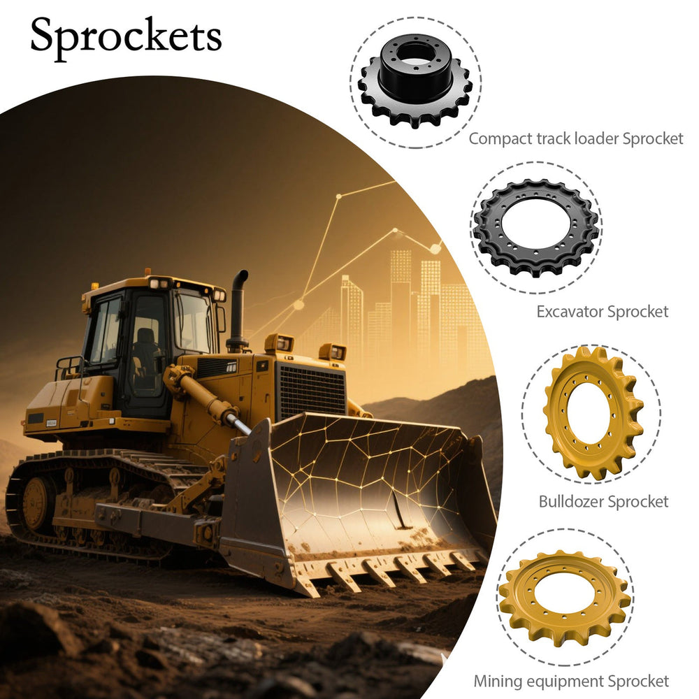
A CAT 336D mud‑relief sprocket is a toothed drive rim whose saddle zones between adjacent teeth incorporate recessed slots or pockets designed to give compacted soil and clay controlled escape routes as the track chain engages. Compared with solid sprockets, which present continuous metal at the saddle, mud‑relief rims intentionally remove material in non‑load‑bearing regions to create low‑pressure cavities.
As the chain bushing seats and loads build, clay is driven into these cavities and extruded away from the primary contact surfaces. By limiting how much mud can remain as a rigid wedge between sprocket and chain, mud‑relief sprockets aim to keep effective chain pitch closer to nominal, preventing hidden over‑tensioning and preserving smoother rolling contact.
On CAT 336D‑class excavators working in cohesive clays, such sprockets become a key element in stabilizing track tension, protecting links and rollers, and keeping final drives from absorbing shock loads caused by sudden spikes in resistance.
Pain points: solid sprockets in sticky clay
Chain packing and tension spikes
Solid sprocket pockets behave like closed molds. As teeth drive the chain, sticky clay is trapped between bushing and saddle and rarely has an easy path to escape. With repeated rotations, this clay compacts and densifies rather than shedding, effectively increasing apparent chain pitch and forcing the track to run tighter.
Operators experience this as a machine that feels harder to travel or swing, even though the adjuster was set correctly. Hidden over‑tensioning loads idlers, rollers, bushings, and seals. In severe cases, it contributes to cracked links, premature chain stretch, and irregular tooth wear patterns.
Accelerated wear and thermal loading
When packed clay cannot escape, the sprocket tooth ends up climbing the chain instead of rolling it. The interface shifts from mostly rolling to a mix of rolling and sliding, which increases frictional heating at tooth flanks and bushing surfaces. Clay caught in this zone can glaze into an abrasive layer that behaves less like mud and more like fine sandpaper.
Over time, this thermal and abrasive environment produces scalloped sprocket teeth, polished but thinning bushings, and shortened service life for the entire undercarriage. These effects often appear long before chain pitch or tooth profile trigger obvious replacement alarms.
Maintenance downtime and unsafe clean-out practices
Crews facing chronic packing frequently resort to manual clean‑out using bars, hooks, or shovels around the sprocket while the machine is stationary but recently operated. Even when lock‑out procedures are followed, workers face pinch points, unstable footing, and residual heat.
In deeper clays or seasonal wet periods, machines may come off production every day for pressure washing around sprockets and chains. This creates direct labor cost and significant indirect cost in lost operating hours, especially for fleets with tight schedule commitments in mining, quarrying, or infrastructure projects.
Track geometry deviation and guidance loss
Clay doesn’t always pack evenly. As material builds asymmetrically around the drive rim, it can skew chain alignment slightly off the intended running line. That skew influences how links enter idlers and carrier rollers, potentially driving lateral wear on guide teeth, flanges, and side plates.
The result is a compound problem: not only are sprockets and chains wearing faster, but guidance integrity across the undercarriage deteriorates, making subsequent alignment and replacement more complex.
Comparative overview: mud-relief vs solid sprockets
To make the differences concrete, it helps to compare three typical configurations for CAT 336D‑class machines: engineered mud‑relief sprockets (such as those produced by KTSU), standard solid sprockets, and generic aftermarket rims with simple pockets.
Key behavioral differences
| Feature / Outcome | Engineered mud‑relief sprocket (CAT 336D-class) | Standard solid sprocket | Generic aftermarket sprocket with basic pockets |
|---|---|---|---|
| Mud escape path from saddle pockets | Recessed slots or cavities tuned for controlled extrusion and discharge. | No dedicated escape path; pockets close as clay compacts. | Simple cut‑outs with limited tuning to chain geometry. |
| Risk of track tension spikes in sticky clay | Reduced by lateral and outward extrusion of clay as links roll through. | High; packed clay increases effective pitch and tightens track. | Moderate; relief helps but misaligned geometry can still trap mud. |
| Wear behavior on bushings and teeth | More consistent rolling contact, less sliding from packing. | Increased sliding, higher friction and localized bushing wear. | Variable; depends on hardness and pocket shape. |
| Maintenance clean-out frequency | Lower; mud expelled during operation under most clay conditions. | Higher; frequent manual or pressure clean‑out in clays. | Moderate; features help but may clog or bridge. |
| Compatibility with high-quality chains and rollers | Designed to work with precision‑machined chains and hardened rollers as a system. | Compatible but offers no mitigation for packing issues. | Compatible; performance often inconsistent across brands. |
| Lifecycle cost impact | Potentially lower through reduced wear and downtime in cohesive soils. | Higher due to accelerated wear and more frequent stoppages. | Intermediate; improvements over solid but less optimized. |
From a fleet manager’s perspective, the question “Is it worth switching from a solid sprocket to a slotted one?” usually boils down to clay exposure, downtime cost, and component quality. In sticky environments with high utilization, an engineered mud‑relief design tends to justify itself over a replacement cycle, while generic pockets may offer only partial relief.
How mud-relief slots actually work under torque
Mud-relief geometry and chain engagement
Mud‑relief sprockets place cavities in the saddle zone between adjacent teeth, often offset slightly from the exact midline. This offset allows the roller seat to remain structurally solid while directing trapped clay toward the recess rather than deeper into a blind pocket.
Slot geometry matters:
Deep enough to accept meaningful volumes of clay.
Narrow enough and tapered to preserve structural strength in load‑bearing paths.
Positioned so rollers and bushings never seat directly in the void, avoiding misalignment and impact loading.
As the chain rotates, each bushing passes through a repeating cycle: entry, seating, load, extrusion, and exit. The mud‑relief cavity is designed to interact with that cycle, encouraging clay to flow out of the high‑pressure contact zone into lower‑pressure volume.
Clay extrusion as a quasi-fluid
Under high drive torque, clay behaves like a plastic material with a yield stress. Once contact pressure at the bushing–sprocket interface overcomes that yield stress, clay begins to deform and flow, even though it remains cohesive.
In mud‑relief designs, pressure rises as the bushing moves into the saddle and clay has two choices: compress into a rigid wedge or move toward the nearest low‑pressure region—the slot. Carefully shaped trapezoidal or curved cavities bias this choice toward movement, guiding clay into thinner ribbons or chunks that are extruded outward and eventually discharged.
The process is not perfectly steady. Moisture content, particle size, and temperature all affect how quickly clay yields and how completely cavities clear between rotations. That’s why operators may observe periods of excellent self‑cleaning followed by temporary bridging, especially in highly plastic clays.
Dynamic control of tension spikes
The operational goal of mud‑relief geometry is not to keep sprockets spotless, but to prevent progressive tightening caused purely by packing. By expelling a portion of clay each time a bushing passes through, the design limits how much material can accumulate as a rigid spacer over multiple revolutions.
Track tension still relies on correct adjuster settings and regular inspections. Mud‑relief slots simply remove one major variable—unmanaged clay wedges—from the equation, stabilizing load on idlers, rollers, and final drives and reducing surprise spikes that occur without any mechanical adjustment.
Real-world usage scenarios
Heavy excavation in river clay
A CAT 336D excavator digging trench in high‑plasticity river clay on repeated passes faces chronic chain packing in solid sprocket pockets by mid‑shift. Crews stop to manually clean pockets using bars and hoses, losing productive hours.
Switching to mud‑relief sprockets matched to the machine’s chain geometry changes the pattern. Clay is extruded through tapered slots under torque, pockets stay more open, and unplanned stoppages shrink. Track tension readings taken before and after shifts stay closer to the initial setpoint, indicating reduced packing‑driven tightening.
Infrastructure projects with mixed soils
On road‑building or urban infrastructure work, machines cycle between granular base, compacted subgrade, and intermittent sticky backfill. Operators often ignore early signs of packing until tension rises, at which point bushing and tooth wear are already accelerated.
With mud‑relief sprockets in place, every rotation gives clay an escape route. Frictional heating decreases, bushings retain more of their original profile, and chains maintain usable pitch longer. For mixed‑soil projects, the main benefit is extending undercarriage life and flattening the maintenance curve, rather than eliminating packing completely.
Quarry overburden in wet seasons
Quarries frequently encounter clay lenses in overburden during wet periods. Solid sprockets may require daily pressure washing to keep chains from running tight and to avoid unsafe manual clean‑outs around the rim.
Standardizing on CAT 336D‑compatible mud‑relief sprockets and properly machined chain assemblies gives clay a continuous extrusion path. Cavities still require inspection, but overall clean‑out labor drops and machines stay available for productive digging longer. Safety exposure at pinch points and hot surfaces also decreases, which matters in high‑activity quarry environments.
Cross-component system thinking: KTSU undercarriage combinations
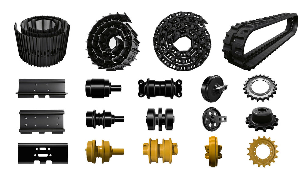
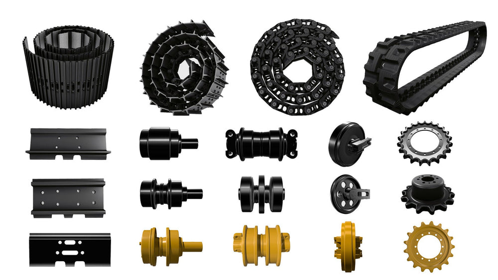
Mud‑relief sprockets perform best as part of an integrated undercarriage system rather than as isolated replacements. KTSU’s catalogue covers:
Track rollers and carrier rollers
Front idlers
Track chains and link assemblies
Track shoes and rubber tracks
Fasteners and associated hardware
For fleets dealing with tension spikes and packing on CAT 336D sprockets, pairing mud‑relief rims with dimensionally precise chains and hardened rollers from the same design family offers several advantages:
Geometry compatibility: sprocket tooth profile and chain pitch are developed together, reducing misalignment risk.
Hardness balance: rollers, bushings, and teeth share compatible hardness ranges, helping avoid one component becoming a sacrificial wear point too quickly.
Wear profile consistency: from idler to sprocket, components are tuned to wear in predictable patterns, making replacement planning more accurate.
In practical terms, specifying KTSU track roller and carrier roller assemblies alongside mud‑relief sprockets helps maintain consistent guidance and load distribution, while matching link and chain assemblies ensures reliable engagement when clay extrusion behavior is part of the design.
Step-by-step: reducing chain packing and tension spikes on CAT 336D sprockets
1. Assess soil conditions and packing risk
Start by mapping typical ground conditions across projects or sites. Identify segments where cohesive soils—plastic clays, silty clays, loams—contact sprockets for prolonged periods. Machines working mostly in dry granular soils gain less from mud‑relief slots; those in sticky clays gain the most.
Pay attention to seasonal changes: what looks manageable in dry months may become a chronic packing problem when rainfall increases or groundwater levels rise.
2. Inspect current sprocket and chain engagement
With the machine safely locked out and supported, examine how sprocket saddles engage chain bushings. Look for:
Glazed or compacted clay in pockets
Polished but uneven wear on tooth flanks
Flat spots or abnormal wear patterns on bushings
Evidence of sliding marks instead of pure rolling contact
These signs suggest that clay is not escaping cleanly and that the sprocket is climbing the chain more than intended.
3. Specify mud-relief sprockets matched to CAT 336D geometry
When selecting replacements, avoid generic rims with oversized cut‑outs that aren’t tuned to chain geometry. Instead:
Choose sprockets designed specifically for CAT 336D‑class excavators, with documented pitch and tooth profile compatibility.
Prefer engineered mud‑relief cavity designs over simple voids, paying attention to offset positioning, depth, and taper.
Where possible, source sprockets and chains from the same design ecosystem, such as KTSU’s assemblies, to reduce cross‑brand geometry mismatch.
4. Install with correct alignment and torque
Follow installation procedures carefully:
Clean mating surfaces and inspect hubs for distortion or wear.
Apply recommended torque values and patterns to fasteners.
Rotate the track slowly and check chain seating through full revolutions, watching for binding, uneven contact, or bushing engagement with relief cavities.
Misalignment can negate mud‑relief benefits and, in severe cases, introduce new failure modes.
5. Set and monitor track tension in real soil
After installation and initial tension adjustment, test the machine in representative clay conditions:
Take baseline tension readings in a clean area.
Operate for a defined period in sticky ground.
Recheck tension and note any significant increases that aren’t caused by mechanical adjustment.
Proper mud‑relief behavior should reduce progressive tightening caused purely by packing, but it will not compensate for incorrect tension settings, worn adjusters, or damaged springs.
6. Integrate mud-relief sprockets into preventive maintenance
Add specific steps to undercarriage inspections:
Visual checks for slot blockage and saddle cleanliness
Monitoring of wear profiles on teeth and bushings
Recording of packing incidents and clean‑out frequency
Correlation of these data with soil conditions, projects, and seasons
Over time, this information can guide component choices, replacement intervals, and even jobsite practices, aligning undercarriage management with real‑world clay behavior rather than generic schedules.
Failure modes: when mud-relief slots don’t solve the problem
Mud‑relief sprockets reduce chain packing and tension spikes, but they are not a guarantee of clean operation in every soil or usage pattern. Understanding their limitations helps avoid false expectations.
Slot clogging and bridging
In extremely plastic clay or clay mixed with fibrous debris, relief cavities may bridge and clog, turning into solid plugs instead of flow paths. Once the cavity is filled with material that resists extrusion, it behaves more like a solid saddle, and packing resumes.
Operators may notice this as a gradual return of heavy travel feel and rising tension despite having mud‑relief sprockets fitted. Periodic cleaning or adjustments to operating patterns (for example, allowing longer continuous runs rather than stop‑start motions) may be necessary.
Erosion of relief walls
Over time, wear on tooth flanks and relief walls can change the intended flow path. If erosion enlarges cavities to a size that encourages bushings to seat toward the void rather than the designed seat, roller support is compromised and contact patterns shift.
When relief areas become too large or poorly defined, sprockets can begin to exhibit impact loading, misalignment, and abnormal tooth wear. In such cases, the mud‑relief design has effectively ceased to function and the rim behaves more like a worn solid sprocket with irregular pockets.
System-level issues
Even with ideal mud‑relief geometry, other undercarriage factors can override its benefits:
Incorrect track tension settings
Severely worn or stretched chains
Misaligned or damaged rollers and idlers
Inconsistent hardness or geometry across mixed‑brand components
Mud‑relief features are not a replacement for system‑level maintenance. They address packing‑related tension increases, but they cannot correct errors in installation or neglect in inspection and adjustment.
When mud relief is not enough: where else packing happens
Relief in the sprocket gives material one route out. If packing continues after relief sprockets are fitted, the constraint is elsewhere in the undercarriage, and four places are worth checking.
| Where material packs | What it does | What to check |
|---|---|---|
| Between the rollers and the frame | It holds the chain away from the surfaces it should roll on and can lock a roller | The clearance around each roller, and whether the frame has openings that let material fall through |
| Inside the track frame channel | It changes the geometry the chain runs in and adds weight in the wrong place | Whether the channel drains, and where the machine is parked overnight |
| Between the links, in the chain itself | It resists articulation, which loads the pins and bushings and prevents the chain seating properly | Whether the chain can be cleared by operating or needs to be washed and worked free |
| Around the idler and the adjuster | It prevents the adjuster travel that holds tension | The adjuster travel after cleaning, since a seized or packed adjuster changes the reading you are taking |
Two consequences follow. The first is that relief in a component is not the same as drainage in the machine: the sprocket can only let material out of its own pockets, and everything upstream of it still has to let material go. The second is that the cleaning routine is part of the specification decision: a machine working in clay needs both the design and the discipline, and the design alone does not compensate.
The practical test is one shift: clean the machine, work it, and look at where material has collected before cleaning again. That single observation tells you whether the relief is working and which part of the undercarriage is actually holding material.
KTSU expert views on mud-relief design
From KTSU’s engineering perspective, mud‑relief slot design is a balancing act between cleaning efficiency, structural strength, and manufacturability. On sprockets sized for CAT 336D‑class machines, the radial band between tooth tips and hub offers limited space for cavity shaping, hardening, and machining.
Engineers have to ensure:
Relief cavities offer enough volume and taper to encourage extrusion.
Load paths through tooth bases remain robust against repeated torque cycles.
Heat treatment and welding near slot edges produce smooth transitions rather than ridges that trap clay.
Japanese design practices around contact stress modeling and finite element analysis help visualize how bushings and teeth share load across seats and relief zones. Chinese manufacturing capabilities allow those designs to be realized at scale, with friction welding and CNC machining keeping tolerances consistent across thousands of parts.
Field feedback from distributors working in Southeast Asian clays, North American sticky soils, and European mixed sites feeds back into R&D. Reports of slot clogging, uneven wear, or unexpected tension behavior drive incremental changes: slightly adjusted taper angles, localized hard facing, or depth refinements targeted at specific chain models.
From an expert standpoint, mud‑relief slots should be treated as a tuning parameter inside an undercarriage system, not a standalone fix. When chains, rollers, idlers, shoes, and tension practices all align with the mud‑relief design intent, fleets see smoother travel, more predictable wear, and fewer sudden tension events. When those surrounding factors diverge, the slots’ benefits can be muted or even lost.
Frequently Asked Questions
What do mud-relief sprockets actually do?
They give compacted material a path out of the tooth root so it is not carried round the sprocket and into the chain. The feature keeps the running geometry closer to the design in ground that packs.
Why does packing continue after relief sprockets are fitted?
Because the sprocket can only clear its own pockets. Material can still pack between the rollers and the frame, in the frame channel, between the links, and around the idler and adjuster, so the constraint may be upstream of the sprocket.
How does packing damage the undercarriage?
It changes the geometry the chain runs in, holds the chain away from the surfaces it should roll on, and can lock a roller. The damage appears on the link rail and the roller flanges rather than on the material.
How do I find where the packing is happening?
Clean the machine, work a shift, and look at where material has collected before cleaning again. That observation identifies the part of the undercarriage that is actually holding material, which is not always the one the design change addressed.
Does cleaning frequency change with the ground conditions?
It has to. Clay and wet soil pack and then set, which is worse than loose abrasive material, so the machine on that ground needs the cleaning at the end of every shift rather than a weekly wash.
This article is part of Undercarriage Problems in the Field: Mud, Clay, Snow and Water, the guide that covers this topic in decision order.
More Maintenance & Wear guides
Find the next article for your component, application or buying decision.
Back to Maintenance & Wear